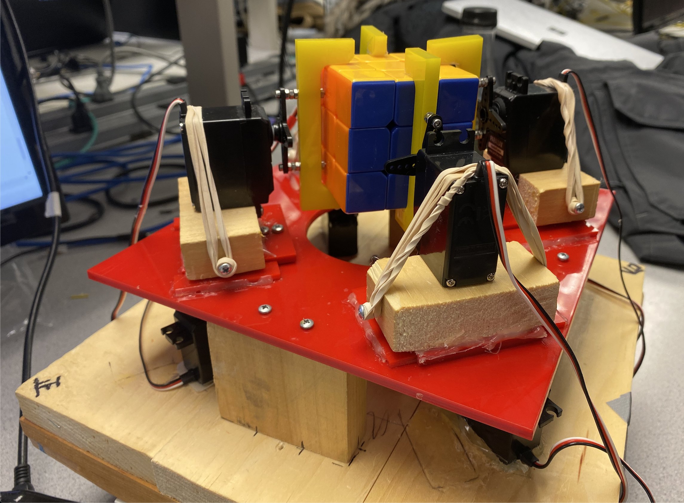
(1) Mechanical Setup and Hardware Designs:
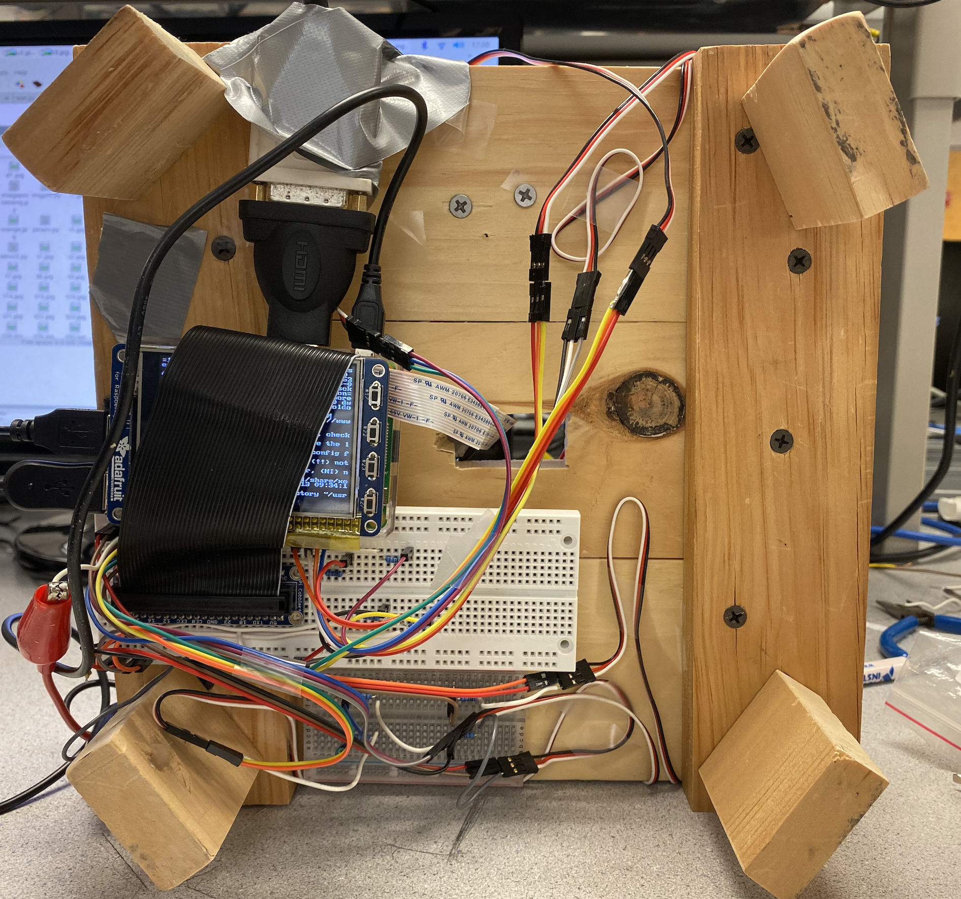
Figure 2 Hardware connections
a. Three Layers
There are three layers in total. The first layer is designed for placing circuits , connections with outside
equipment such as keyboard, mouse, monitor and RPi. All the wires are connected from this layer. The second
layer is for placing standard servos that are used for directional movements. Besides, the Pi camera is also
placed on this layer. This layer is made of wood. The third layer which is also made of acrylic is used for
placing servos that are for controlling the claws rotationally. This is also where rubik’s cube is placed.
The height between the first and the second layer is around 5cm and the height between the second and the third
layer is around 6.7 cm which is suitable for the Pi camera to take picture of the face of the rubik’s cube.
The third layer are designed with four slides where the 4 servos on the second layers can easily control the
claws to move on the slides and go forwards and backwards. Also, there is a 5.5 cm circular hole in the center
where Pi camera takes pictures through the hole and records the faces of the rubik’s cube. Detailed
design is presented in Figure 2-1. This is achieved by Fusion software and laser cut.
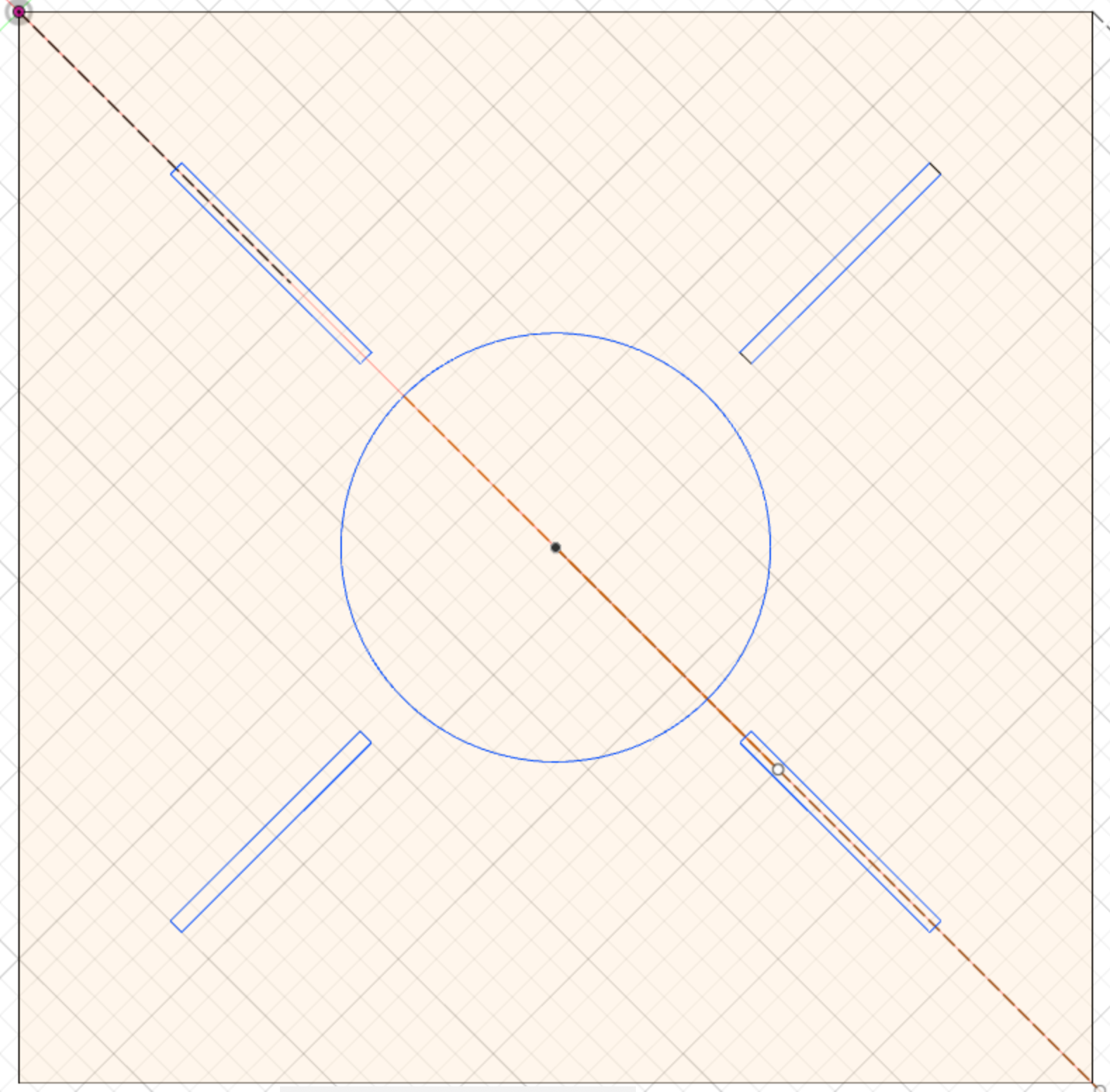
Figure 2-1 Design of the third layer
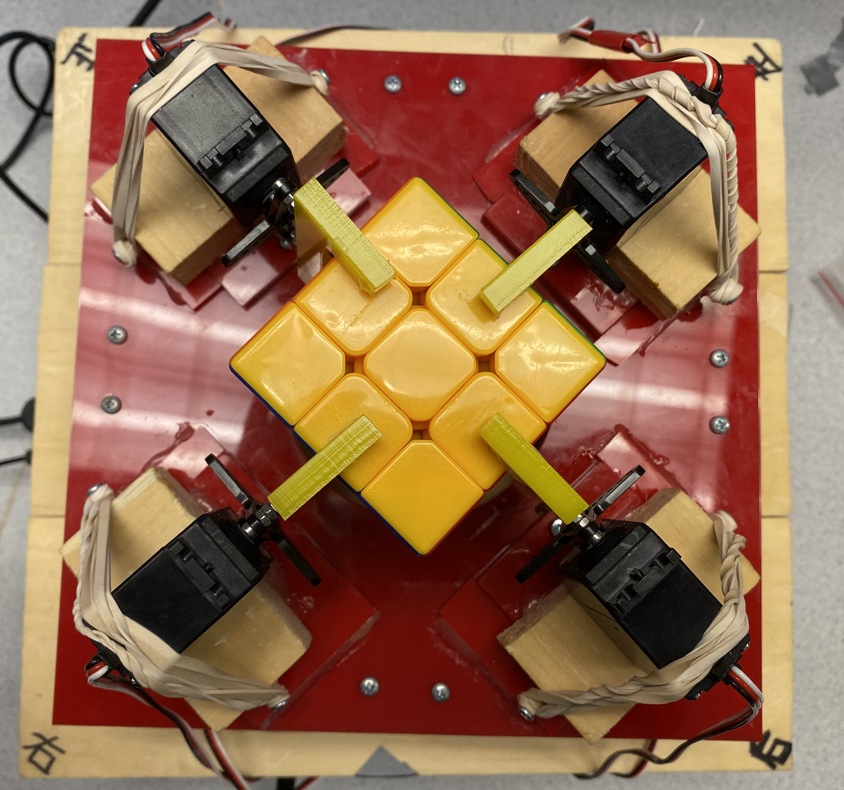
b. Claws
There are four claws to control the four sides of the rubik’s cube. The length of a claw is design to be
slightly wider than the size of the cube so that we can attach tape on contact surface in order to perfectly fit
the claws with the cube. As Figure 1-1 suggests, we apply rubber bands to adjust the orientations of the claws.
The design of the claw is presented below, and this is also achieved by Fusion software and laser cut.
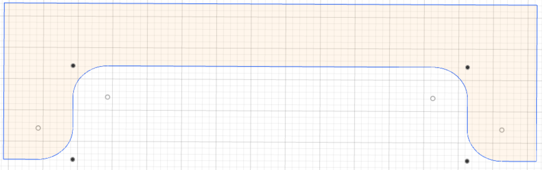
Figure 2-2 Design of claw
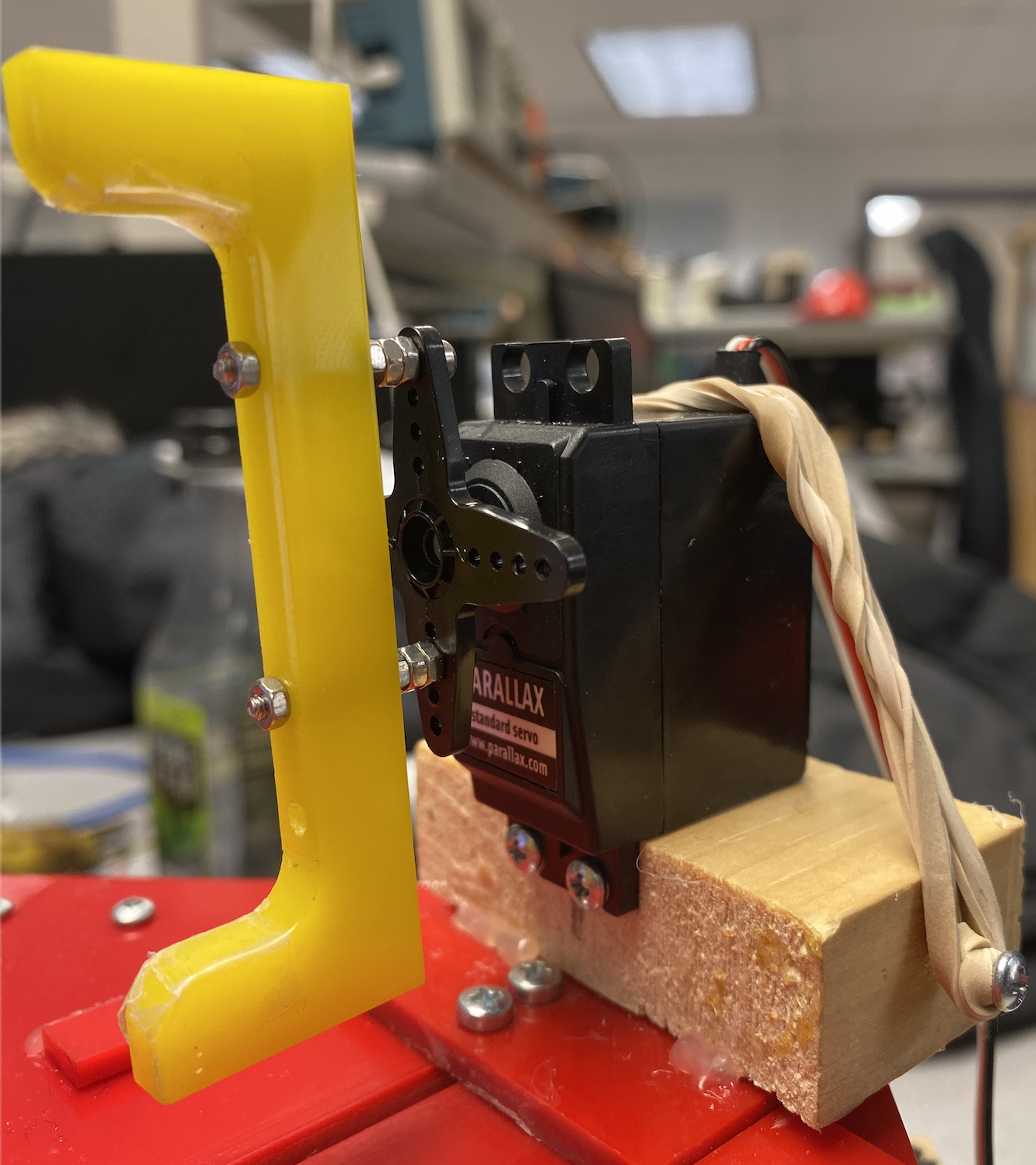
Figure 2-3 Graph of claw
(2) Software Designs:
a. Standard Servo Controls
As mentioned before, there are 8 servos in total. 4 standard servos are served for controlling the claws to
move forwards and backwards, the other 4 servos are for rotational controls. The software control of the servos
are as below: Each servo has three connections: 5V Power Supply, Ground and GPIO pin. Servos are controlled
through PWM. Duty cycle and period are used to determine the directions of the servos
(clockwise/counter-clockwise) and the rotation angles of the servos(90 degrees/180 degrees).
The GPIO pins that are used are: 6, 5, 13, 26, 21, 19, 16, 12.
b. Camera Program
In order to take pictures of each side of the cube, a program related to this function is written. In order to
eliminate the number of operations, we first take pictures of the back side, upper side and front side. This is
because that they are on the same axis. After that, we take pictures of the left side and right side. It is
worth mentioning that the rotational range of the servo is between 0 degree and 180 degrees. Therefore, we need
to be careful of the current state of each servo in order to prevent mistakes.
c. KNN-based Image Recognition Algorithm
In order to recognize the color of each square of the rubik’s cube, machine learning is applied for
recognition. 30 different 40x40 images are used for training set. The reason for setting size as 40x40 is that
it is convenient since the average value has already been calculated. RGB is applied in the project during
machine learning. When analyzing one color, we divide the color into R value, G value and B value and they are
trained respectively. 30 different images mean that each color will have a size of 45 training set. The value of
K is set as 3 after testing.
In order to prevent mistakes, in recognition process, the average value of a range of pixels is calculated. For
example, for the upper-left square, the average value of the pixels whose x-axis are [9,12] and y-axis are
[9,12] is considered.
The flowchart is as below:
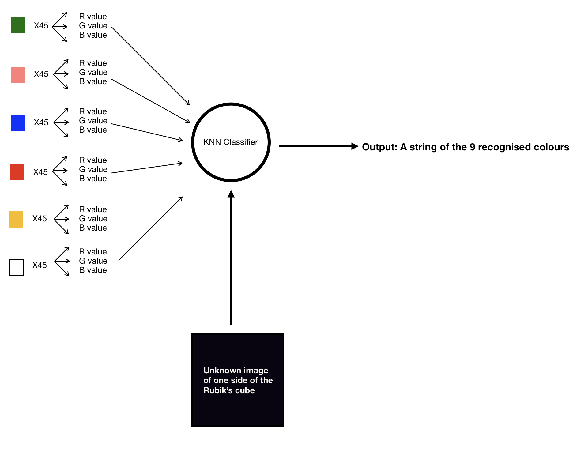
Figure 2-4 KNN classifier
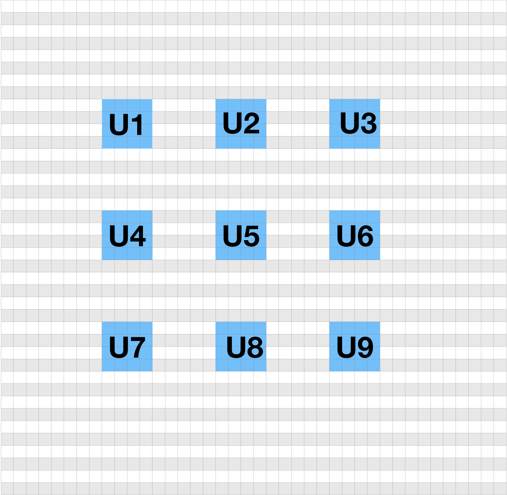
Figure 2-5 An example of taking average of a range of pixels
d. Kociemba Algorithm
After taking pictures of each side of the rubik’s cube. The recognition results are placed into one single string following the order: “U1U2U3 U4U5U6U7U8U9R1R2R3R4R5R6R7R8R9F1F2F3F4
F56F7F8F9D1D2D34D5D6D7D8D9L1L2L3L4L5L6L7L8L9B1B2B3B4B5B6B7B8B9” and the corresponding numbers are based on Figure 2-5.
By importing package “Kociemba” and apply this string as input: “kociemba.solve(‘U1U2U3U4U5U6U7U8U9R1R2R3R4R5
R6R7R8R9F1F2 F3F4F56F7F8F9D1D2
D34D5D6D7D8D9L1L2L3L4L5L6L7L8 L9B1B2B3B 4B5B6B7B8B9’)”. The solution will then be returned through a single string for
example: “U U2 F’ B’ B2 F2 R”. A single letter : U/F/B/R/L/D means the corresponding side need to be rotated
clockwise 90 degree. A single letter with the number ‘2’ like ‘U2’ means this side need to be rotated 180
degrees. A single letter followed by an apostrophe means the face need to be rotated counterclockwise 90
degrees.
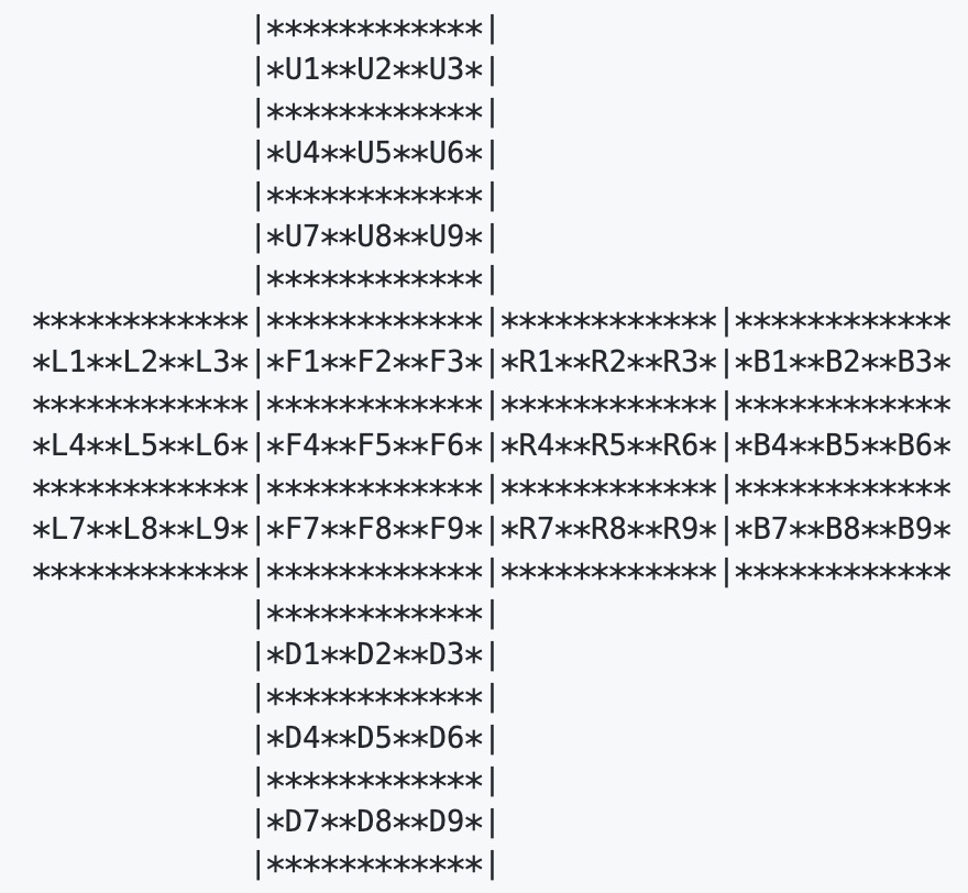
Figure 2-6 Facelet position of the cube
e. Claw Operations
Basic operations where more complex operations are based on need to be defined in advance. Basic operations
include: clockwise rotation for front, right, left and back side. Counterclockwise rotation for front, right
left and back side. More complex operations include rotations on upper side and down side, rotations over 180
degrees.
Here is an example of rotation on front side:
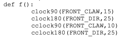
Figure 2-7 Example of basic claw rotation
First, the servo for rotational movement rotates 90 degrees, and then the claw is dragged out by the servo for
directional movement. The claw the rotates counterclockwise 90 degrees to get back to the initial state. After
that, the claw is placed back to the initial location.
Future Improvements
(1) Short summary of this project
This is a challenging project that requires really high standard of accuracy of the servos. We spent around
2-3 weeks for the mechanical construction and another 2-3 weeks for image processing and adjustments on claw
rotation acuuracy. The image recognition works well when the colours are scattered. However, it may fail to
reciognize when there is side where the majority colours are red, orange and yellow. Besides, for simple
operations, the claws work well. However, there are some rotational errors when flipping the whole cube.
Although we have tried very hard during this 5 weeks, we failed to have all the functions work as expected. The
image recognition part need to be improved and the cube rotations should be more accurate.
(2)Improvements
a.Image recognition
Initially, we applied basic image processing for color recognition. We set a range for the R, G and B values
for each color. Whichever color that satify the range will be recognised as the corresponding color. This method
works fine when the location of the robot does not change. However, due to the changes of outside environments
such as light intensity, it fails to recognise the colors.
We applied image recognitin with supervised machine learning techniques instead. KNN classifer was chosen for
recognition as it is simple and easy to implement. It does work better than just simple image processing.
However, when there are many red, orange or yellow colors on one side, the contrast would result in making
orange colors very close to red colors. This causes some mistakes on recognition.
For future improvements, we can apply OpenCV techniques to detect the location of the cube first, and then
recognize the colors.Besides, we can have a larger training set in order to improve the recognition accuracy.
Also, as what professor has suggested, we may tuned the Picamerain order to have the camera focus on the face of
the cube. Some LEDs can also be added to light up the whole image.
b.Rotation Accuracy
In this project, what we did to improve the accuracy of the claw rotations is to adjust the PWM cycles and PWM
duty cycle step by step. However, this is obvious not an efficient and clever way. Moreover, since the servos
are not perfect, they can still become inaccurate even when we apply a perfect PWM signal. Therefore, this is
not an ideal solution.
Based on this, the future improvements should be by adding some feedbacks on each operation. By doing so, the
robot can adjust the next operation based on the current errors. One possible way to do it is to apply IR
diodes. They can be placed besides the cube and see if the receiver can received the IR signal. If not, it means
that the cube is twisted so that it blocks the routine and therefore some operations need to be taken in order
to prevent further mistakes. This could be one posible solution for rotation accuracy.